Originally ratified in the IEEE 802.1D standard, spanning-tree protocol (STP) is used ubiquitously throughout enterprise networks to prevent layer 2 network loops. With STP, traffic on physically redundant paths between bridges (or switches today) is blocked to form a logical loop-free topology. It's a fundamental technology all network professional have studied. Yet, there's one topic that isn't often covered. In this post, I'll briefly introduce STP's Topology Change Notifications (TCNs) to help bridge the gap.
TCN overview
Topology Change Notifications are a type of Bridge Protocol Data Unit (BPDU) generated by non-root bridges in response to links going up or down. When an STP bridge detects a change in link status on one of it's ports, it generates a TCN and sends it via its root port towards the root bridge. The TCN is then relayed up the tree by other bridges until it reaches the root bridge. Upon receipt of a TCN, the root bridge then notifies all other bridges in the topology by setting the topology change bit in its outgoing configuration BPDUs.
Why are TCNs needed?
Ultimately, TCNs provide a mechanism to quickly flush MAC address tables when STP topology changes occur. Without such a mechanism, traffic can be black-holed when changes happen. Let's look at an example.
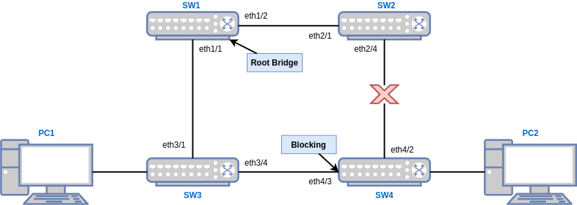
SW1 is the root bridge, and eth4/3 on SW4 is blocking. PC1 is running a continuous ping to PC2. The link between SW2 and SW4 has just gone down. Here's what would happen in classic 802.1D spanning-tree if we didn't have TCNs:
- PC1's pings no longer complete because the path to PC2 is interrupted.
- With no traffic from PC2, the default 300 second MAC aging timer begins counting down on SW1 and SW3.
- Within 50 seconds, STP reconverges as the link between SW3 and SW4 is no longer blocked.
- Unless PC2 originates traffic (which would be unicast flooded), PC1's pings continue to be black-holed on SW2 while it's MAC address table entries slowly expire over 200+ seconds.
This is the problem that TCNs solve. Here's what happens with TCNs:
- PC1's pings no longer complete because the path to PC2 is interrupted.
- Both SW2 and SW4 detect that the link went down.
- SW2 generates a TCN and sends it via it's root port to SW1.
- Since the link that went down was SW4's root port, it cannot send a TCN.
- SW1 receives the TCN from SW2, and sends a TCA back.
- SW1 sets the Topology change bit in its configuration BPDUs.
- Both SW2 and SW3 receive the TC bit in configuration BPDUs from SW1.
- SW1, SW2 and SW3 all set their MAC address aging timer to the STP forwarding delay timer (15 seconds by default).
- Within 50 seconds, STP reconverges as the link between SW3 and SW4 is no longer blocked.
- By this time, PC2s MAC address is no longer cached on SW1, SW2 or SW3. When PC1 sends traffic destined for PC2's MAC address it is unicast-flooded and learned by SW4 via SW3.
- Return traffic from PC2 is now sent via the link between SW3 and SW4 where its MAC is also cached.
- Traffic between PC1 and PC2 once again flows normally.
Increased unicast flooding
Reducing MAC address aging timers on all switches in the topology each time a port transitions to or from the forwarding state causes additional unicast flooding. Normally this isn't a concern since topology changes should be rare. However, port flapping, and ports that connect directly to end-devices can be problematic. In these cases where the TC bit is set repeatedly, unicast flooding can cause a large amount of broadcast traffic that can saturate lower bandwidth links.
802.1D was also created in a world where bridges and hubs were commonplace. An end-device on a hub going up or down wouldn't have caused a TCN to be generated since upstream links to bridges wouldn't have changed state. Today, however, with switches used at the access edge, every access port can potentially cause a TCN to be generated.
To help avoid unnecessary TCNs and unicast flooding caused by end-devices coming and going, Cisco implemented a proprietary feature called PortFast. PortFast allows you to specify which ports connect directly to end-devices. Ports configured with PortFast are assumed to be loop-free and skip the listening and learning states, immediately transitioning to forwarding. In addition, TCNs are also not generated when the state of a PortFast enabled port changes. An equivalent "edge port" feature was later standardized in 802.1w, Rapid Spanning-Tree Protocol (RSTP). Yet, it is still configured using the portfast keyword on Cisco switches.
TCN handling in RSTP
In 802.1w, Rapid Spanning-Tree Protocol (RSTP) included major improvements over classic 802.1D STP. In addition to standardizing many of Cisco's proprietary enhancements to 802.1D like "edge ports", and significantly changing how convergence works in general, it also updated the process by which bridges are notified of topology changes.
Detecting topology changes in RSTP
In common 802.1D STP, a topology change is detected and a TCN generated whenever a port transitions in or out of the forwarding state. In RSTP, a topology change is only detected when a non-edge port moves into the forwarding state. That means a link failure isn't actually considered a topology change.
Considering the topology in our example from before, when the link between SW2 and SW2 fails, RSTP wouldn't see this as topology change. A topology change would only be detected when the link between SW3 and SW4 transitions from discarding to forwarding (this would happen immediately since SW3 eth4/3 would be in the alternate port role).
Topology change propagation in RSTP
With common spanning tree, TCN BPDUs are only ever relayed up to the root bridge. The root bridge then sets the TC bit in configuration BPDUs which are propagated back down the tree to all bridges. RSTP instead cuts out the root bridge--in fact, TCN BPDUs aren't even used in a purely RSTP network. Instead, each RSTP bridge sends it's own configuration BPDUs and sets the TC bit when a topology change is detected, flooding it out all non-edge ports.
As with 802.1D STP, the action taken upon receiving a BPDU with the TC bit set is to flush learned MAC address. With RSTP, however, this process occurs much more quickly. Instead of setting the aging timer equivalent to the forwarding-delay timer, each bridge immediately flushes all MAC addresses learned on its ports except the port the TC bit was received on. This drastically reduces the amount of time it takes for connectivity to be restored, but can result in more temporary unicast flooding.
Conclusion
Spanning-tree's Topology Change Notification mechanisms help avoid black-holing traffic caused by stale MAC address table entries when topology changes occur. The original 802.1D STP standard uses a TCN BPDU to notify the root bridge which then notifies all other switches by setting a TC bit in configuration BPDUs. 802.1w RSTP switches, on the other hand, directly originate their own configuration BPDUs and thus don't need to send TCNs to the root. In both cases, however, the goal is to quickly flush switch MAC address tables. While this temporarily causes additional unicast flooding, it also ensures that connectivity is restored quickly whenever topology changes occur.
Comments
comments powered by Disqus